This is the homepage of the paperBalázs Bank, "Passive Admittance Matrix Modeling for Guitar Synthesis ," Proceedings of the 13th International Conference on Digital Audio Effects (DAFx-10), pp. 3-8, Graz, Austria, Sept. 2010.
 Abstract
In physics-based sound synthesis, it is generally possible to incorporate a mechanical or acoustical immittance admittance or impedance) in the form of a digital filter. Examples include modeling of the termination of a string or a tube. However, when digital filters are fitted to measured immittance data, care has to be taken that the resulting filter corresponds to a passive mechanical or acoustical system, otherwise the stability of the instrument model is at risk. In previous work, we have presented a simple method for designing and realizing inherently passive scalar admittances, by composing the admittance as a linear combination of positive real (PR) functions with nonnegative weights. In this paper the method is extended to multidimensional admittances (admittance matrices). The admittance matrix is synthesized as a sum of PR scalar transfer functions (second-order filters) multiplied by positive semidefinite matrices. For wave-based modeling, such as digital waveguides (DWGs) or wave digital filters (WDFs), the admittance matrix is converted to a reflectance filter. The filter structure is retained during conversion, resulting in a numerically robust implementation. As an example, a dual-polarization guitar string model based on the DWG approach is connected to the reflectance model parameterized from guitar bridge admittance measurements.
 Sound examples
The examples below were computed for the lowest (E) guitar string using a dual polarization digital waveguide string model. The excitation is modeled by setting the initial displacement of the string to a triangle shape. The outputs of the admittance model were the bridge forces parallel (z direction) and perpendicular (y direction) to the top plate of the guitar, and the sound radiation was modeled by two 200th order parallel filters, one for each force direction. The radiation filters were estimated from impulse responses recorded in an anechoic chamber. (Note that radiation modeling is not discussed in this paper. You may check my ICMC07 paper and it's sound examples page for details.)
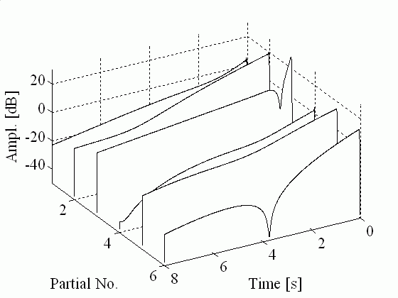
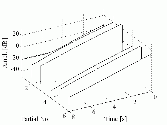
For comparison, the sounds are also computed for a resistive termination. In that case, the coupling is frequency independent, and in practice this means that the two waveguides are coupled by constant coefficients. Also, because the admittance is resistive, only (some) two-stage decay occurs, while for the admittance filter case beating also appears. (Try to listen to the evolution of partial envelopes and see the figures below.)
Pluck direction 60th order passive admittance filter Resistive admittance Perpendicular to guitar body (outwards) EXC Y EXC Y Res Parallel to guitar body (downwards) EXC Z EXC Z Res 45 degrees EXC YZ EXC YZ Res The following figures show the partial envelopes for the 45 degrees excitation cases. The difference in the curves is striking, so it is rather surprising that the audible difference is much more subtle.
Partial envelopes for the guitar model using the passive admittance filter
Partial envelopes for the guitar model using a resistive admittance (constant coupling coefficients)
See my other publications!
Last modified: 04.09.2010

